BMS (Battery Management System) || DIY or Buy || Properly protecting Li-Ion/Li-Po Battery Packs
BMS (Battery Management System) || DIY or Buy || Properly protecting Li-Ion/Li-Po Battery Packs
 $2 for 10 PCBs (No fee on any color): https://jlcpcb.com
Previous video: https://youtu.be/pMc_H-REIJk
EBike Battery Pack video: https://youtu.be/b2sBhDxmPmA
Facebook: https://www.facebook.com/greatscottlab
Twitter: https://twitter.com/GreatScottLab
Support me for more videos: https://www.patreon.com/GreatScott?ty=h
Websites which were shown during the video:
https://www.youtube.com/channel/UCZm-Gp9v5KH98bQwkAxyF3w
https://www.youtube.com/channel/UCm5sG3-BXQZfVy3st2T_XKg
https://github.com/stuartpittaway/diyBMS
https://github.com/chickey/diyBMS
http://hmsemi.com/downfile/DW01A.PDF
https://datasheet.lcsc.com/szlcsc/HYCON-Tech-HY2213-BB3A_C113632.pdf
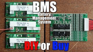
In this episode of DIY or Buy we will be having a closer look at BMS or battery management systems. That means I will show you how a commercial BMS is built and how it functions. Afterwards I will then have a look at a DIY BMS project from Stuart Pittaway, build it and test it in order to find out whether you should stick to the commercial BMS or use a DIY one instead. Let’s get started!
Thanks to JLCPCB for sponsoring this video
Visit https://jlcpcb.com to get professional PCBs for low prices
Music:
2011 Lookalike by Bartlebeats
Killing Time, Kevin MacLeod
(incompetech.com)
7:46 OK bruh just why
Sorry but after years of working with ev power trains I can only state one thing:
I’m absolutely baffled by stupidity of people NOT to understand that BMS shall disconnects all it’s connections to the battery cells when it recognises that cell voltage fell WAY to low, and only readable it self when charging is provided and slowly retest the battery and figure out whenever battery is dead or safe to charge !
That stupid mistake is causing more fires than people think !
4:30 In this BMS case, could the output resistors be increased to charge the battery not to 4.20-4.25V, but to a maximum of 4.1volts, in balanced mode????
This modd, would significantly increase battery life, and it would be very important to change this! 4.1V = + 30-40% charge cycle lifetime! If anyone knows, please let me know here!
Nice explanation on the "Buy" options… one point I’d make is, that the DW01 works in tandem with MOSFETs, not "simple" Transistors. Yes, I know, MOSFETs technically are transistors, but you did make a distinction, when talking about the big Power MOSFETs… so… just my two pennies on the matter.
Jordi Motorway
Great video, very informative, can I ask you a question. I have a 60v battery i am working with at the mo that has the 2+1+5 discharge connector I can’t seem to get power from or only low power, the ground to the discharge side of the bms is 70v so I’m guessing one of the other wires must go to ground to make the circuit or a resister, I can not get a diagram for the board 2 power feeds then a 6 pin connector with 5 wires, first 2 wires are twisted together one goes to a resister, fz, the second is marked lock the third is rcst then dport then toot then pim_iso 🤷♂️ any help would be much appreciated
What happens if a battery charge gets low? Does the BMS shuts itself off to avoid draining the battery?
But my system uses lifepo4….
To confirm, does the voltage/cell monitoring function use the same cables as the balancing?
So some of the BMS you find that look like yours and are sold on several platforms (amazon, ebay, or aliexpress) do not actually do as they claim. I bought one almost identical to your only 3s version… it almost ruined my pack. I have a nearly perfectly balanced pack (50mAh variance out of 30 000 mAh total). The issue is that is somehow managed to make 2 of my cell banks (3s16p battery) were discharged to 0 volts and one was at 4.3 volts… Not good. None of my cells had any measurable self discharge before this happened, and I have been attempting to find out what is now causing the self-discharge, whether it’s the BMS or if the cells now have a self discharge. I didn’t even get one charge out of the pack. Only the initial charge was usable (I charged each cell to full to test for self-discharge and so they’d all be the same SoC for assembly).
I saved the pack with a small active balancer, and thankfully the over charge and over discharge protections all worked on the BMS or it would have started my pack on fire.
Maybe mine is defective, but I’ll have it investigate later. In any case I would recommend an active balancer on any large pack. They actively balance at any voltage so they can be used even you limit the charge to between 20% and 80% to extend cycle life… and they’re a LOT faster than bleeding off the cells since every amp you drain from the highest cells goes to the lowest cells so it’s almost like balancing twice as fast… while making less heat. Though some of them have low current so I just get one that has low drain ( less than a miliamp) and leave it connected so it can just always balance and I never have to worry about it. Realistically, the DIY BMS with the 1 amp bleeder resistors is faster than cheap active balancers because of that giant 1 amp of current… the bleeder resistors in most commercial BMS boards are way way smaller and are thus going to be slower than active balancers and are only going ot activate at a set voltage which is set by the BMS circuit rather than programmable software.
That purple marker completely smudging the ink of the numbers and letters really pissed me off more then i would want to admit. For esthetical reasons please consider an alternative.
if you pay more you get better bms.
Can you explain lifepo4 battery bms and lithium ion battery bms to lifepo4 battery to charge can you make
My jbl xtreme2 always blinking at 5 led light indicator and it not automatically off sir 😔
Cells are already worn out once you charge them to 4.3 or 4.4 V. Rather than charging them to a high voltage and then balancing, charging them not in series but individually would be much better solution.
Contact please so can we do something
hi it is very good to find you here. could you tell me wat is dual stack motor and how does it work?
There are no microcontroller in the BMS?
One question what is the connection of the power resistance
The power resistance say R004 on it
Means its 0.04 ohm
Their are 3 of them
If they r in parallel the resistance value wood be 0.001 ohm and the voltage at 35 amp 0.46 volt i think this could the case
If the resistance is series the resistance will be 0.12 ohm the voltage will be 4 something volt
And low of heat
Which one is correct?
https://youtu.be/_8yEHdrNCVI?si=nCNqeNZIU2nQ9PEH
Hello brother, I have a 3s 40A bms setup for my batteries, yesterday they worked fine but today as soon as i connect a load the Output voltage of the BMS drops to 6V from 11V making the load inoperable. This board is even new already threw one 3S 25A board for facing similar issue. Pls resolve or guide me if u know.
when load gets disconnected BMS shows Op again to 11V…each battery has 3.78, 3.79 and 3.80V
I wonder if instead of the big resistor being used to drain a full battery is a passive balancing style that this excess power could be used to charge the cells that need the extra power in an active balancing style?
YOU ‘ RE THE MAN!
How do you make a 400V battery management system with 108 3.7v batteries with 6 in parallel and 18 batteries in series?
I like it and I do want a help to learn arduino programming
Nice.
hey scott could you please recommend me the best bms for a 2s7p 18650 pack that i am building for a kids electric ride car?
thank you.
But Scott where is balance discharging feature??
buy was better
good explanation, Thanks for sharing.
i was planning to use it to charge my drone batteries.
But ended up buying 4ch 4s charger for 60eur.
Im glad i did, at the end.
Is it possible to use LiPo BMS with Li-ion cells?
I have a dead powerbank (using LiPo cells & BMS). I want to reuse this BMS by connecting Li-ion (NMC) cells. Is it a stupid idea?
Looking into a project that will require a 128s BMS, great info!
the English… so painfull
Why do you bother with a Mickey Mouse Arrangements
You didn’t do a good job of measuring the resistor in the current limit. Measurement with two wires can never be accurate because the resistance of the cables themselves is also introduced. In order to take an accurate measurement, 4 wires must be used. The value of the current limiting resistor is 0.0013 ohms, not 0.05 ohms. The protection activation voltage is probably 50mV
well done
Hello. What is the component model at 0:34? Would it work with a 12V sealed lead-acid battery? Thanks!
would the commercial one work for modifying a powertool battery pack? most modern power tools have bms in the tools not the batteries. the bms board would protect the battery during usage and the charging cycle of the battery is managed by the commercial charger
At the end in couple of shots it shows voltage calibration value exceeding 4.4v and you mentioned the charge exceeded the set 4.1v and boards balanced them out. So does that mean they got as high as 4.4 and then the DIY BMS brought them down back to 4.1v? Was did it allow to charge that high in the first place?? That is really bad / high voltage for battery life.
foxBMS PCBA, https://www.youtube.com/watch?v=wvT09qzAMdk
"My pack got 4 cells in serious ". Yeah, really, I’m being serial !
Can a BMS for 18650 cells used for 21700 cells? Someone answer pls 🙏
I have a 36v battery pack. It’s a seperate port bms. It charges to 42v however when I test the neg and positive out it reads 20v. This is an older lithium battery pack that came from a scooter. What components could cause the output to read 20v? Everything is factory made. The pcb board and batterys work before. But no longer can discharge becsuse the bms read 20v and the battery at its neg and pos ends read 42v. Is it a bad mosfet?
Hi great scott, kindly help in arduino programming
Wow , Holy Scott ,…… nicely explained project,…….
Please do some 4S BMS ´, Lifepo when possible ,.
Every body is not does have programming skill 🙏
can we charge every string of batteries by e 4.2 charger module by Connect them individually with 3 modules for 3s and charge it with a single port typ c ???
When you have a BMS would a (one way) -> diode be best to use ? See I been using the BMS board but when connecting to LED switches the boards been short circuit.
Does this board draw current when the pack is supposed to be shut off?
Very nicely done. Has anyone made this "universal" – capable of supporting any voltage and any battery chemistry?